


Tunnel building
Modern Shield Tunnel Construction for the Metro 4 Line
In our era tunnels are constructed under extremely various rock conditions, under live waters, mountains, high rock pressure, urban environment or near railway stations, sometimes under thin cover. That is why different shield types and construction technologies need to be applied. Thanks to the gained construction experience more and more new solutions have been developed. We can say that there is at least one approved method for even the most peculiar situation encountered.
Tunnelling shields designed for the construction of the first phase of Metro 4 line in Budapest are considerably different with respect to the open face shields used earlier in similar works for the east-west and north-south lines in Budapest.
The modern tunnelling shields manufactured today, which can be considered for the tunnel construction of Metro 4, are suitable for the management of any problem possibly emerging during tunnelling, as confirmed by the international tunnelling practice for tunnel boring under sees and rivers, through high pressure karst waters under the Alps etc.
The special requirements for the tunnelling shield, obtained from detailed surveys carried out along the alignment, will be enforced within a contract concluded with potential contractors, as set out in technical specifications complying with local characteristics and stipulated by strictly established technical specifications.
What Kind of Technology Will Be Applied?
A very important consideration in selecting shield type is that it should be suitable for boring in all soil types occuring between the start (Kelenfldi pu Station) and end points (Keleti pu Station). Since in general the sub-soil on the Buda side is hard (marl) no water ingress is expected, the so called open face shield with cutting cross may also be used. On the contrary, under the Danube and on the Pest side, a closed face support shield is required.
Similar differences in soil conditions also occur within the same tunnel in the case of other projects, that is why multi-purpose tunnel boring shields have been developed ("Mixshield" or "Polyschield"). Such shields can be modified from open face to closed face support without removing the shield itself. Such modification was envisaged by the designer at Szent Gellrt tr station. From this point on, the shields are advanced with closed face support under the Danube and in the entire Pest side section. The closed face tunnelling ensures that neither rock collapse nor large water amount of any origin may retain or flood the shield.
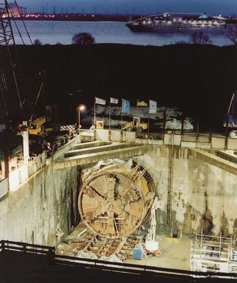
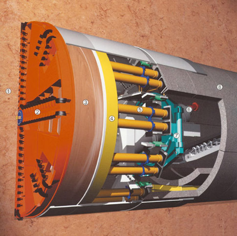
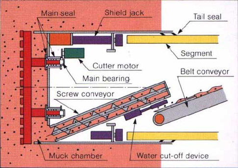
The external structure of the shield consists of a closed steel cylinder and a boring-support disk. The revolving disk excavates the rock ahead, driving the rock through the disk opening of adjustable size into the work chamber, which is separated by water-proof steel wall from the back of the shield. The muck in the working chamber is mixed with bentonite slurry. The slurry containing the muck can only be transported through a closed pipeline to a separator equipment located on the surface. The pipeline can be closed any time by gate valves. New slurry is also supplied through closed pipeline from the surface through the tunnel into the closed front chamber. Overpressure of the slurry can be adjusted. This adjustment enables to compensate the earth and water pressure at the face in compliance with the particular hydrostatic pressure.
The system can immediately react to the sudden appearance of a large amount of water under pressure at the face, namely karst water. If water accidentally gets into the closed system it may only cause increase in chamber pressure. However, such occurance cannot hinder shield driving. Shield advancement results in blocking the water creek at the face. The shield and the tunnel wall will act together as a plug blocking water flow within the shield/tunnel wall.
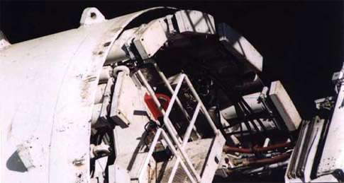
The tunnel wall consisting of segments can be assembled ring by ring within the shield tail plate using the erector located at the shield back. The rings are connected with bolts and a rubber or plastic sealing system that can immediately provide waterproof wall. Thus, no water can filtrate into the tunnel through the wall either.
The shield is pushed forward by built-in pressing machines supported by the last installed ring element. The gap between the shield tail plate and the tunnel wall is closed by a sliding waterproof seal and, in emergency situations, a second inflatable sealing ring.
Apart from the front chamber, there is no overpressure inside the shield. The system described above actually prevents any water beyond leaking to filtrate into the tunnel.
Another shield type differing from the above one, but with similar results, is the so called earth pressure balance (EPB) shield. The face is supported by a mass consisting of muck and some additives. In order to facilitate boring and transportation, an additive is mixed into the muck, which can be either water, bentonite or foaming substance.
This shield type can provide sufficient safety against water ingress. Compared with the a hydro-shield the difference is that the compensation of pressure changes due to sudden geological, hydro-geological changes (water ingress) is slower. The modification of the shield from cutting cross operation to EPB is similar to that described at the bentonite slurry method.
Local survey of the rock located 8 to 10 meters directly in the front of the shield occurs through survey borehole through a sealing gland structure installed in the shield shell. It is possible to take the necessary measures in due time depending on the rock conditions revealed in this manner.
Whenever necessary, a watertight screen can be injected around the shield through the sealing gland boring or grouting holes. In slurry shield tunnel driving presented above two materials are used that can be direct contact with the rock or the karst water: bentonite slurry and cement mortar injected to fill the annular gap. The bentonite, since it consists of clayey minerals, cannot cause any pollution in the environment since in any section only clay is present in the soil.
The bentonite slurry serves to continuously support the rock surface in front of the cutting head of the shield and to prevent possible water ingress. Slurry pressure can be adjusted by compressed air. The quantity of the slurry pumped in, and that of the transported muck is also continuously controlled, thus,no harmful cavities are formed.
Since support pressure higher than the earth and water pressure at the shield face is not needed, the system is virtually in balance all the time. Bentonite slurry could only get into the tunnel if it was exposed to a pressure higher than necessary. However, this is not possible in an automatic control system preventing human errors and technological failures.
In case of EPB shield, foaming and homogenizing additives are mixed into the muck enabling easy transportation. The muck, treated this way or untreated, is transported through the tunnel to the surface. The used foaming additives are environment friendly substances approved by international practice, with chemical and biological degradation capability.
The annular gap around the tunnel is filled with fast-setting cement mortar as soon as the segment ring appears after the shield tail plate following shield advancing.
Composition of the grouting cement mortar enables that only larger cavities can be filled, and that setting occurs in a controlled manner and in due time following grouting. An additive preventing washing-out can be added to the cement mortar. In this phase the mortar can fill only smaller or wider cracks located directly next to the tunnel, and not farther cavities.
(For that matter, the tunnel is located at least 170 m away from spring group 1 withdrawn from production in 1979.)
In order to ensure higher level of safety in the section under the Danube, the bolted connections of tunnel segments may remain in place for a longer period that usually required, until the completion of consolidation or even forever.
Total water-tightness of the pre-cast tunnel segments made of water-proof concrete and sulphate resistant cement is provided by neoprene waterproofing installed in the grooves on segment fronts. As secondary waterproofing, and for the case of a possible tunnel fire, the grooves of segments are filled by heat-resistant and fire-proof material. The structure of segments enables a posterior water-proof grouting if required.
Consequently, the tunnels of Metro 4 may be constructed using modern, closed face tunnel driving shields and including the application and reasonable use of construction technologies approved in practice, electronic control system, as well as integrated up-to-date geophysical karst water monitoring systems. The special tunnel section under the Danube may also be constructed, without any risks to change the karst water base in terms of either quantity or quality. The selected construction technology ensures to construct the metro tunnels with minimum surface settlements and acceptable risks despite soil and ground water conditions present on the Pest side.
Considerations for the selection of construction technology for Metro 4:
- Geological, engineer-geological, soil mechanical conditions of the rock environment.
- Hydro-geological conditions (position and characteristics of ground water, confined water, karst water).
- Soil cover above tunnel and engineering structures.
- Horizontal and vertical alignment (gradients etc.).
- Geometry of the tunnel and engineering structures (cross section, length of sections). Characteristics of the built environment (building density etc.).
- Considerations of the natural environment.
- Expectations of the human environment (noise, vibrations, dust, transportation etc.).
- Considerations of the economic efficiency.
- Construction time.
- Building and environment protection regulations (Concept of the Metro design, National Railway Regulations, authority requirements etc.).
Alignment sections on the basis of the selection criteria for tunnelling technology:
- Section 'A' in Buda
- Section 'B', crossing under the Danube
- Section 'C' in Pest
Section 'A' in Buda
The rock enables the following construction technologies for running tunnels on the Buda side:
- Mining method with shotcrete technology
- Shield tunneling
- Combinations of the two technologies
Section 'B', crossing under the Danube:
In this section, two models of the closed face support shield can be considered:
- Hydro-shield with bentonite slurry
- EPB shield,
- Combined shields ("Polyshield", "Mixshield" etc.).
Section 'C' in Pest
As at the crossing under the Danube, closed face support shields can be used.
- Hydro-shield with bentonite slurry
- EPB shield,
- Combined shields ("Polyshield", "Mixshield" etc.)